Power Supply and Chassis Assembly
The power supply stabiliser circuit is shown in Fig. 12. Here the diode D5 will prevent damage if incorrect connection to the power source is made. The supply to the main amplifier and multivibrator is taken from the Zener diode D4, and that for the meter circuit is additionally decoupled by R33 and C21.
Three separate chassis connections, G1-G3, are made between the main amplifier and stabiliser to prevent the possibility of oscillation.
The supply lead from the 12V battery must be screened. The centre wire is positive and terminates at SK5; the negative screen at SK6. Constructional details are given in Fig. l3. Since the magnetometer draws about 750mA during “polarise”, an adequate heavy duty power source must be used.
Meter Amplifier
The circuit for the meter amplifier is given in Fig. 10. Here VR2 acts as a sensitivity control in feeding the complementary pair TR10 and TR11. The meter circuit can be used in conjunction with, or to replace the headset.
The meter needle follows the amplitude of the amplifier output which varies at a rate equal to the difference between the two input frequencies. It is particularly useful with very low difference frequencies.
Constructional details of this module are given in Fig. 11.
Amplifier Construction
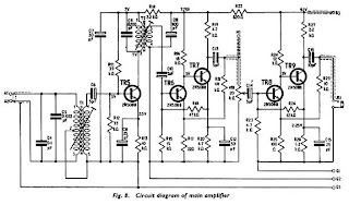
Since the amplifier provides high gain, the wiring layout and constructional details of Fig. 9 should be adhered to, to prevent instability. Both of the transformers are contained in Vinkor adjustable pot cores. To wind T1 use 40 s.w.g. enamel covered wire. Slip a couple of inches of fine sleeving over the start to protect the leadout, then wind on seven hundred and fifty turns. Put on another piece of sleeving over the finish leadout and wrap a layer of cellotape round the winding.
Put on two more windings of three hundred and seventy-five turns each and identify the starts and finishes with different coloured sleeving. Wind a layer or two of plastic electrical tape around the completed winding then very carefully assemble the bobbin in the ferrite core. Ensure that nothing gets trapped between the two halves of the core, preventing them mating.
Main Amplifier
The output from the secondary of T2 feeds the d.c. coupled amplifier TR6-TR7. This acts, in effect, as a pre-amplifier to the meter circuit, the input for this being taken from M1.
Relay Driver and Multivibrator
Circuit Blocks Proton Magnetometer
Now look at the block schematic of the magnetometer in Fig. 5. There are in effect six units comprising: two detector bottles, relay circuit, multivibrator, main amplifier, meter amplifier, and power supply. These form what might be called a de-luxe unit. The relay and meter circuits may be omitted if costs have to be kept down.
BASIC MAGNETOMETER
 12:50 AM
 Proton Magnetometer Precicion
, Posted in
Basic Proton Precession Magnetometer
,
0 Comments
intensity of the earth’s field is the same at each bottle, the precession frequency at each will be the same, and the signals from both coils of equal frequency.
Atomic Principles
 12:45 AM
 Proton Magnetometer Precicion
, Posted in
Basic Proton Precession Magnetometer
,
0 Comments
Proton Precession Magnetometer
They are used in land-based archaeology to map the positions of demolished walls and buildings and at sea to locate wrecked ships for recreational diving.
The principle of operation is outlined in the magnetometer article.


