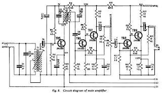
Main Amplifier
The main amplifier, seen in Fig. 8, serves to increase the level of the precession voltages. A ferrite cored transformer, T1, with the primary centre tapped, is tuned to the required frequency by C4 and C5. The first stage comprising TR5 has a tuned collector load resonant at the same precession frequency.
The output from the secondary of T2 feeds the d.c. coupled amplifier TR6-TR7. This acts, in effect, as a pre-amplifier to the meter circuit, the input for this being taken from M1.
The bandwidth of the tuned circuits is about 300Hz, which has proved adequate on field trials. VR1 is the volume control for the headphone amplifier, TR8-TR9, the output being taken via JK1.
The headphones used should preferably be high impedance crystal, since magnetic ones can cause feedback trouble if brought too close to the detector bottle, and so cause the amplifier to oscillate. (In field trials magnetic phones were used and proved
trouble-free provided they were maintained in the plane of the
detector bottles.)


 7:02 AM
 Proton Magnetometer Precicion
, Posted in

0 Response to "Main Amplifier"
Post a Comment